EM61 Quality Control for Ordnance Explosives OE Digital Geophysical Mapping
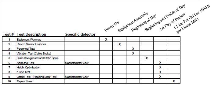
U.S. Army Engineering and Support Center standard equipment tests and data quality requirements for Ordnance Explosives – Digital Geophysical Mapping OE-DGM contractors.
These are different than found the procedures found in “Geophysical Investigations with the Geonics EM61-MK2 and EM61- Operational Procedures and Quality Control Recommendations.”
Nonfunctioning and incorrectly functioning equipment is a source of frustration, inaccuracy, and time delays before geophysical investigations. Locating Ordnance and Explosives requires the upmost accuracy. In order to efficiently and successfully perform these surveys, complete the required operational procedures to assure functionality and quality control. Note that only quality control tests for the EM61 are included on this page. Other tests are within the PDF, authored by the U.S. Army Engineering Corps, at the bottom of the page.
EM61 Quality Control for OE Digital Geophysical Mapping
1. Equipment Warm Up
Allow readings to stabilize allowing the EM61 to warm up for at least five minutes. This reduces the amount of themal drift.
2. Record Relative Sensor Positions
Document relative navigation and sensor offsets, detector separation, and detector heights above the ground surface. This will ensure that detector offset corrections and gradient calculations can be done correctly and that the surveys are repeatable.
Acceptance Criteria: +/- One inch (2.54 cm)
3. Personnel Test
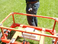
Remove all sources of interference from your body. Common sources of interference include steel toe boots, keys, coins, and ballpoint pens. After removing all obvious sources of interference, the operator should walk close to the EM61 coils while an observer notes any changes in the EM61 readings. Acceptable variation is +/- 2mV.
4. Vibration Test
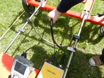
Identify and replace cable shorts and broken pins on the connectors. After concluding the Personal Test, continue to keep the EM61 in a static position while collecting data. Ask an assistant to observe the data while you shake each EM61 cable. Begin shaking a cable from the one side and continue to shake until you reach the other end so that the full length is tested. The assistant should be looking for any spikes in the data resulting from the movement. If a spike occurs, that cable needs to be replaced. Make certain to test any replacement cables.
5. Static Background and Static Spike
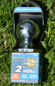
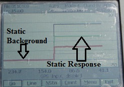
Note instrument response drift, locate potential interference spikes in the time domain, and determine response and repeatability of the instrument to a standard test item such as a 2” steel trailer hitch ball.
Find an area free of metal and anomalous noise/responses. Unstable readings are caused by encompassing noise such as EM transmissions from power lines or an instability in the earth’s magnetic field.
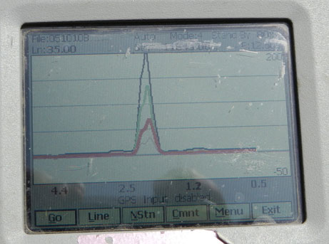
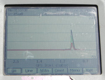
Place the EM61 in the test area at its normal height and orientation, turn it on, and begin recording data. After the EM61 is warmed up, watch the readings for at least three minutes. Next, place the test item below the coils and collect data. After one minute, remove the test item. and collect readings for another minute. Review the readings to confirm their stability prior to continuing with the geophysical survey. Readings should consistently be +/- 2.5 mV during the Static Background Test whereas the Static Spike test response should be +/- 20% of standard item response, after background correction.
The Static tests may help when trying to determine the proper scale for the 6 Line Test described below given that you use the same test object.
6. Height Optimization
This test can be used with the EM61 if used in the harness or “litter” mode. Create a test line and place a small test object along this line. Travel along the line at least three times at different heights. Note which height delivers the best signal to noise ratio that reliably detects the smallest test object.
7. EM61 Quality Control – Six Line Test
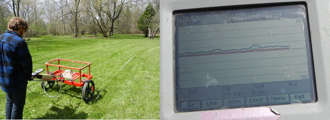
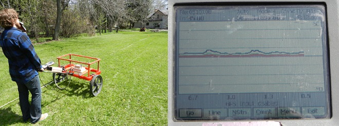
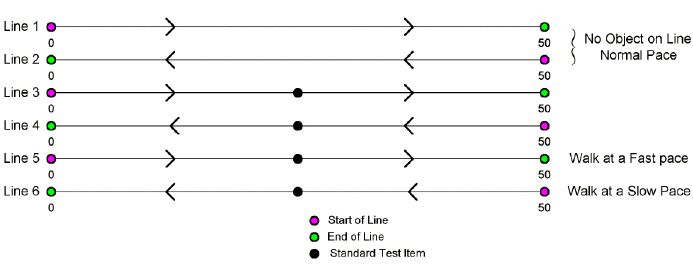
Before any geophysical investigations, perform the 6 Line Test. Power up the EM61 and allow it to warm up for 2 to 5 minutes. Find an area that has little interference and no deviating responses. Identify and clearly mark your test line. Keep one wheel on or very close to your line to ensure that the same path is taken for each line run.
Line 1: At a normal pace, begin to collect data along the test line. At the end of the line, pause your recording and turn around.
Line 2: Take a second recording along the test line. These two lines are to establish the background noise over the test area.
Next, use a standard test item such as a 2” steel trailer hitch ball to use for the following four test lines. Stick the steel trailer ball into ground so that the orientation of the test item is the same at all directions.
Line 3: Take a third reading along the test line to receive baseline readings of the EM61 test item and the GPS location of the test item. Take note of the EM61 reading and the GPS reading when going over the test item.
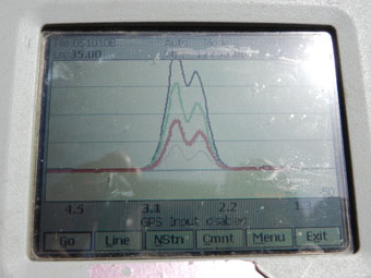
Line 4: Take a fourth reading to verify heading effects and the repeatability of the response amplitude. Heading effects are any EM61 reading changes caused by the EM61′s direction and/or orientation. Likewise, the amplitude of the response to the test item should be +/-20%.
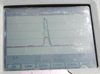
Line 5: Next, take a fifth reading, walking at a slow pace. Observe if there is any latency (time delay) in the reading when passing by the test item. Also, note the GPS location of the test item compared to the reading in Line 3; the positional accuracy of the GPS should be within 35 cm.
Line 6: Last, take a sixth reading, walking at a fast pace. Again, observe if there is any latency (time delay) in the reading when passing by the test item. Additionally, note the GPS location of the test item compared to Line 3; the positional accuracy of the GPS should be within 35cm.
9. Repeat Lines
Determine positional and geophysical data consistency. Use either one line per grid, placed at least 10 feet outside of the grid, or a 100 feet per mile for path surveys that will be repeated before and after the survey. A standard test item should be placed in the middle of the Repeat test line. This line should be free of anomalous noise. The response amplitude of test item for both runs should be within +/-20% whereas the positional accuracy should be within +/- 35cm.
