Geonics EM38 Suggestions and Common Problems
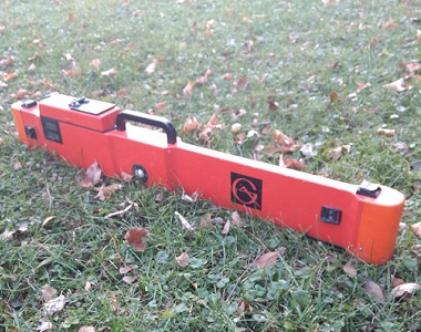
Geonics EM38-MK2
The EM38 is a conductivity meter that measures apparent conductivity in millisiemens per meter and magnetic suceptibility (in-phase component) in parts per thousand of the ratio of the secondary magnetic field to the primary magnetic field. Its working principles are identical to the EM31 but its intercoil spacing is much shorter, making it more suitable to shallower measurements needed for archaeology, mapping soil moisture and stratification, and other agricultural or environmental studies in the near surface.
EM38 Configurations:
The EM38 comes in a couple different variations:
EM38-MK1: The first EM38 unit created by Geonics Limited possessed one transducer and receiver and is known as the EM38-MK1. This unit’s intercoil spacing is 1 meter or a little over 3 feet. This means it can provide data at a depth range of 1.5 meters or 4.5 feet in the vertical dipole and .75 meters or a little less than 2.5 feet in the horizontal dipole. Both components and depth ranges are measured simultaneously.
EM38-MK2: Geonics improved upon the first EM38 by adding an additional receiver coil at .5 meter. Therefore it possesses one transducer and two receiver soils and is named the EM38-MK2. Like the EM38-MK1, the EM38-MK2’s 1 meter coil possesses an effective depth range of 1.5 meters or 4.5 feet in the vertical dipole and .75 meters or a little less than 2.5 feet in the horizontal dipole whereas the .5 meter coil has a depth range of .75 meters (>2.5 feet) in the vertical dipole and .375 meters or about 1.25 feet in the horizontal dipole. All components and depth ranges are measured simultaneously allowing the user to acquire a stratified group of data.
Like the EM31, these depths of exploration are reduced in approximately half if searching for metal.
Future configurations:
Geonics is developing the EM38-4 that possesses 4 intercoil spacings. These spacings are 1 meter, .75 meter, .5 meter, and .25 meter, which takes measurements of each component at depths both 1.5 and .75 times the intercoil spacing simultaneously. In addition, the software contains calculations to do real time inversion at two depths. This unit would allow the user to collect a highly detailed and stratified cross section of the area.
Other considerations:
Most EM38 surveys are conducted by walking along a line with the EM38 hanging from two adjustable straps from a handle that allow the user to collect data close to the ground since it doesn’t make much sense for half the effective range to be air space. The EM38 can also be towed but it is important to null out any effects metal coming from the towing vehicle and/or trailer or sled. Always read the manufacturer’s manual or contact Geonics if trying to null out a towing set-up.
EM38 Site Considerations:
Being an electromagnetic instrument, the EM38 is susceptible to noise from radar installations, TV and radio towers, power lines, and nearby metal objects. In addition, it will pick up other electromagnetic instruments if close enough. Personal objects such as keys, belt buckles, steel toe boots, cell phones and all other metal should be removed from the operator before beginning a survey.
After determining there isn’t any environmental or operator noise, the user needs to find an area suitable for calibration. This area should be free of any metal! Mark this spot as a base station that user can return. Allow the instrument to warm-up for 10-15 minutes to prevent any rapid battery decay from affecting the readings. Use the provided calibration stand and follow the user manual to calibrate the EM38 according to the manufacturer’s directions. The manufacturer recommends performing calibration at least twice a day and more often if the ground is very resistive.
After marking the base station, the user can take a reading at ground level and use this as comparison for any drift due to the following reasons: different time,day, humidity, temperature, or battery power change. It can also be used to compare two or more EM38s and adjust as needed- just remember to keep the units an adequate space apart to prevent interference.
Power and Battery Problems
The EM38 can be either powered by either one 9 volt battery or a battery belt pack. It is important to check the battery every day or when it is suspected of being low. To check the battery voltage, set the Mode switch to BAT. The readings on the display should be between 1500 and 720. If the reading is outside this, replace or recharge the battery. A standard 9 volt battery lasts approximately 5 continuous hours. A large battery pack will last longer.
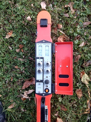
The EM38’s 9 volt battery compartment is located on the top instrument panel next to the display, zero control knobs, mode switches, and trigger. The battery can be assessed by unscrewing two thumb screws and gently pulling the battery cover up, which connects to the 9 volt.
The EM38’s battery pack can be plugged into a female port label “EXT BAT” located on the top display next to the trigger. Be mindful of inserting the battery pack’s male connector into the female battery port as it is keyed.
Remember to always allow any electromagnetic instrumentation to warm up for a minimum of 10 minutes before calibration. Battery decay during initial power-up will cause inaccurate calibration values.
Grid or GPS:
Before starting a survey, the operator must decide whether they want to conduct the survey using a grid or GPS.
Usually when a grid is set-up, the user takes readings in the Manual mode via trigger on a line at given station increments. At each station the user may decide to put the EM38 on the ground to take a reading. Consistent elevation is important for accurate results. The EM38 possesses several different trigger locations. There is a trigger connected to the data cable, on the drop down handle, and on the instrument’s top display.
It usually takes the same amount of time to set-up a grid survey as it takes to collect the data. Lines can be set up to run one way or bidirectional. Grid surveys can be useful for small sites or areas where GPS signal is hard to obtain. For larger grids, it may be useful to break it apart into smaller grid areas. If GPS can be obtain, it would be a good idea to mark corners, obstructions, and points of interest.
Many surveys are used in conjunction with GPS. When GPS is employed, users often opt to collect data in Auto mode. In this mode, readings are continuously taken at preset rate and GPS coordinates as well as time signatures are recorded with each reading.
When surveying, it’s important to balance the amount of data versus the speed of the survey. In general, a reading per second for both the EM38 and GPS is a good starting point. Too large of data files can sometimes present problems when converting in post processing. For this reason, it is always good to divide large surveys into multiple files. It also prevents having to do a large portion of the survey over if something goes astray. Too little data will present the opposite problem and won’t allow interpretative results.
If the user opts to tow the EM38, special considerations must be made. First, the user must absolutely be positive that they performed the proper calibration and nulling in relation to the tow set-up. Second, they must make sure their speed is slow enough that they still properly sample the area. Third, they must ensure the EM38 is staying at a constant elevation or the data will not be consistent.
Sometimes a user may not use a data logger or record data but instead “sweep” the site. In this case, pay attention to the Mode that the user chooses and whether the user is going to hold the EM38 in the vertical or horizontal dipole depending on what depths they want to read. There are 6 mode options.
EM38 Mode Switch
If using a data logger, both quad phase (apparent conductivity) and in-phase will be recorded regardless of what mode is displayed on the data logger or instrument. If sweeping a site without a data logger, pick the proper mode to ensure that the user understands what readings are being displayed:
Off: The instrument is not running.
.5 m: The instrument is in .5 meter mode so the left display will show the quad phase or conductivity and the right display will show the inphase or magnetic susceptibility.
I/P: The instrument is in the inphase mode so the left display will show the .5 meter magnetic susceptibility and the right display will show the 1 meter magnetic susceptibility.
Q/P: The instrument is in the quad phase mode so the left display will show the .5 meter conductivity and the right display will show the 1 meter conductivity.
1 m: The instrument is in 1 meter mode so the left display will show the quad phase or conductivity and the right display will show the inphase or magnetic susceptibility.
BAT: The instrument will show the battery range, which should be between 720 and 1500. If outside this range, replace or recharge the batteries.
Common EM38 Problems and Solutions
The instrument won’t log.
- Is the instrument turned on? Are the batteries low?
- Is the instrument connected via data cable? Are the connections fully seated at both the data logger and instrument?
- Is the data logger cable connected to the assigned Com Port in the Logger Setup menu? Is there a conflict between the assigned data logger com port and assigned GPS com port?
- Is the data cable bad? Did the user try replacing it with the spare?
- Is the instrument enabled in the Logger Setup menu?
- Did the user create a data file and select “Go”?
- If using the NAV program, does the user have GPS signal?
- Did the user try powering the instrument and data logger off and turning it back on?
- If all the above looks correct, the instrument’s data logging INI file may be corrupted. Locate this initialization file and delete it. This file is often in a folder called GEOINI and will have the same name as the logging program followed by the extention “.ini” When this file is deleted, it will reset the data logging program to defaults and all modifications that were changed before the survey will need to be changed again.
The instruments readings don’t change or are maxed out.
- Are the batteries low? Did the user check the batteries after letting the instrument run for 10-15 minutes? Replace or recharge the batteries as needed.
- Is there environmental noise that the instrument is encountering? Is there another source of electromagnetic noise? Sometimes the only method of checking this is to pack up the instrument, move 5-10 miles, and retest the equipment.
- Are all personal metal objects removed from the user? Many users forget to remove their cellphone!
- Was the instrument sufficiently warmed up and calibrated in an environment free of noise?
- Was absolute zero checked? Remember after calibration, the instrument should read zero if held in the air above its greatest depth of exploration.
- Is the tow set-up properly nulled out of the readings?
- Are the anomalies too similar to the subsurface to detect?
- Is the site too resistive? Would electric resistivity imaging be a better method?
- If all the above looks correct, the instrument’s data logging INI file may be corrupted. Locate this initialization file and delete it. This file is often in a folder called GEOINI and will have the same name as the logging program followed by the extention “.ini” When this file is deleted, it will reset the data logging program to defaults and all modifications that were changed before the survey will need to be changed again.