Geonics EM31 Suggestions and Common Problems
Geonics EM31-MK2
EM31 Configurations
The EM31 is a conductivity meter that measures apparent conductivity in millisiemens per meter and magnetic susceptibility (in-phase component) in parts per thousand of the ratio of the secondary magnetic field to the primary magnetic field.
Determine the depth of investigation:
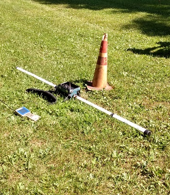
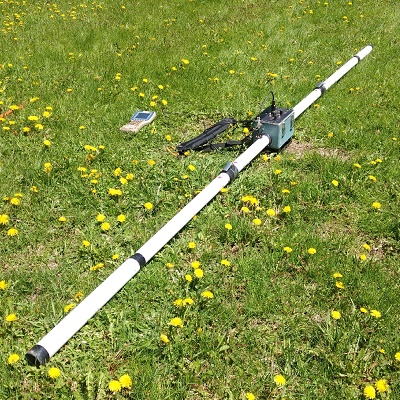
Depending on the depth of investigation, the user may opt to use an EM31-MK2 or EM31 Short. The EM31-MK2 possesses an intercoil spacing of 3.66 meters or about 12 feet, allowing it to reach a maximum depth of investigation of approximately 20 feet in the vertical dipole and approximately 9 ft in the horizontal dipole. The EM31 Short possesses an intercoil spacing of 2 meters or about 6.5 feet, allowing it to reach a maximum depth of investigation of approximately 10 feet in the vertical dipole and approximately 5 feet in the horizontal dipole. When searching for metal as opposed to measuring apparent soil conductivities these depths of investigation are cut in half.
If either unit possesses the ability to reach past the target depth of penetration, it may be advantageous to use the EM31 Short as it is more maneuverable since it is shorter and less cumbersome. Also, it may be easier to use in tough terrain.
The user most likely will want to use a field computer such as Allegro, Archer, TK6000, or Mesa data logger. In rare cases that the user does not log data, but is instead “sweeping” the sight for anomalies, the user may want to request an EM31 with a digital display as some EM31 units do not have a display or are analog. Whenever GPS is used during a survey, a data logger is a necessity.
Future EM31 Configurations:
Currently, Geonics Limited is working on the EM31-8, which possesses eight intercoil spacings that collects both vertical and horizontal dipole measurements at the same time. This allows the user to gather eight different and stratified apparent conductivity readings at a given point at the same time.
EM31 Site Considerations:
The EM31 is susceptible to environmental noise such as radar installations, TV and radio towers as well as nearby metal such as automobiles and fences. The user must remove any personal objects that interfere with readings such as keys, cellphones, or steel toe boots.
After eliminating noise, it is important to find an area for calibration. This area should be free of any metal. Here, the user should calibrate the EM31 after allowing it to warm up for 10-15 minutes, following the user manual for calibration procedures.
The user can also use this site as a base station, taking note of the apparent conductivity readings. These readings can be used to adjust for any drift throughout the day or a span of several days due to temperature, humidity, or battery power change. It can also be used to adjust and compare two or more EM31 units if used on the same site.
Please note that if more than one EM31 unit or any other electromagnetic instrument is used in the same vicinity that there will be noise and the users should use extreme caution that they are not sensing signal from the other units.
Power and Battery Problems
The EM31 is powered by eight C batteries. Two groups of four C batteries create two 6v power sources. Before calibration, the user is going to want to check the batteries by switching the Mode switch to “Oper ” or Operation and the Range Switch to “Batt” or Battery.
The digital display or data logger will show two battery values that should be above +/-4.4 volts. If the batteries are below this, replace them. If the batteries voltages for each “power” source are unbalance, make certain all the batteries are fully seeded in the battery tray. The battery connectors are very tight but can get loosened during shipping if jostled. To check the battery connectors, take the battery tray out, remove the batteries, and pinch the connectors tight before reinserting the batteries. Sometimes, spinning the batteries can help as well. If this does not solve the imbalance, replace all eight batteries.
Remember to always allow any electromagnetic instrumentation to warm up for a minimum of 10 minutes before calibration. Battery decay during initial power-up will cause inaccurate calibration values.
Grid or GPS:
EM31 surveys are usually set up in one of two ways: either a grid or GPS.
When a grid is set up, EM31 readings are taken manually on lines in station increments. The user must physically push a button to record a reading and advance to the next station. Lines can be set up one way or bidirectional. Generally, it takes about the same amount of time to set-up a grid as it does to perform the survey. Grid surveys are useful for small surveys or areas where GPS signal is difficult to obtain. If a grid is the preferred method of surveying, it still might be useful to obtain GPS markers such as the corners of the grid, points of interest, obstructions, etc.
Surveys involving a GPS are usually run in Auto mode. In this mode, readings are continuously collected while the GPS stores associated location coordinates. The user should carefully select the number of conductivity and GPS readings per second. Too little data and results may not be adequate to post process. Too much data can make transferring and processing data more cumbersome. Given the speed an operator can walk, a reading per second is often recommended.
Whether setting up a grid or using GPS, it is always a good idea to split large surveys into multiple data files. This way, if a file becomes corrupted or a tract of land needs to be resurveyed, the user doesn’t need to completely start over.
Common EM31 Problems and Solutions
The instrument won’t log.
- Is the instrument turned on? Are the batteries low?
- Is the instrument connected via data cable? Are the connections fully seated at both the data logger and instrument?
- Is there a bad cable? Did the user try replacing cables one at a time with the spare to rule out a bad connection?
- Is the data logger cable connected to the assigned Com Port in the Logger Setup menu? Is there a conflict between the assigned data logger com port and assigned GPS com port?
- Is the instrument enabled in the Logger Setup menu?
- Did the user create a data file and select “Go”?
- If using the NAV program, does the user have GPS signal?
- Did the user try powering the instrument and data logger off and turning it back on?
- If all the above looks correct, the instrument’s data logging INI file may be corrupted. Locate this initialization file and delete it. This file is often in a folder called GEOINI and will have the same name as the logging program followed by the extention “.ini” When this file is deleted, it will reset the data logging program to defaults and all modifications that were changed before the survey will need to be changed again.
The instruments readings don’t change or are maxed out.
- Are the batteries of sufficient power? Is the power balanced? If not, try replacing the batteries and making sure to pinch the connectors tight as they often become loose in shipping, which will allow the instrument to turn on but not display correct values. If the batteries are new, sometimes taking the batteries out, pinching the connectors, and spinning the batteries ensures a solid connection. Check for corrosion at the terminals and use super fine steel wool to remove any corrosion.
- Is there environmental noise that could affect the instrument’s readings? Is there another source of electromagnetic noise?
- Was absolute zero checked in the 1000 scale with the receiver disconnected?
- Was the instrument sufficiently warmed up and calibrated in an environment free of noise? Sometimes the only way to verify this is to pack the EM31 up and move several miles away and see if noise is picked up in another location.
- Is the Range switch set to a sensitivity conducive to the survey?
- Are the anomalies too similar to the subsurface to detect?
- Is the site too resistive? Would electric resistivity imaging be a better method?
- If all the above looks correct, the instrument’s data logging INI file may be corrupted. Locate this initialization file and delete it. This file is often in a folder called GEOINI and will have the same name as the logging program followed by the extention “.ini” When this file is deleted, it will reset the data logging program to defaults and all modifications that were changed before the survey will need to be changed again.