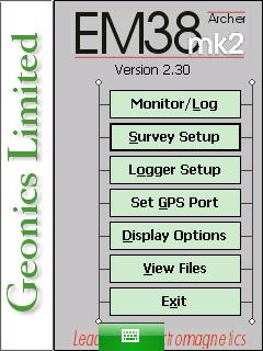
EM38-MK2 Survey Setup Menu on Archer
Configure the EM38 Survey Setup Menu on the Archer.
1. Using the stylus, select the Survey Setup Menu.
2. Select the EM38 Mode.
Select from one of the two modes: Auto or Manual. In Auto Mode, readings will be automatically recorded at a specified frequency. Only one dipole mode, vertical or horizontal, can be selected. This mode is often used in conjunction with a GPS so determine location. The user may want to be aware of their survey speed and determine the proper amount of data collected per second. Too much data can cause issues such as when walking while not enough will leave gaps in the data set if towing the instrument at a speed that is too fast.
In the Manual Mode, readings are manually triggered by the user. Any combination of dipole modes, vertical, horizontal, or both can be selected. Make note that when Manual mode is selected, the option Reading/s changes to the option labeled Samples/Rdg. Manual mode is often used when a user creates a single line or grid.
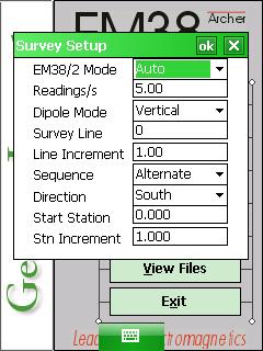
In the Auto Mode, the user must select the number of Readings/s. The Readings/s Field is the number of readings the EM38-MK2 will take per second. Any number above zero can be entered but since the EM38-MK2 has a fixed frequency of data output at 21 readings per second, any value entered will be rounded to the nearest base frequency of the EM31. For example, an entered value of 20 will result in 21 readings.
In the Manual Mode, enter any positive value into the Samples/Rdg Field. This field is the number of readings that will be taken after the trigger is pressed. After the EM38-MK2 is done taking a reading it will beep, average its readings, and plot the data on the screen. The EM38-MK2 can take 20 readings per second. The maximum sampling is 100 readings, which corresponds to 5 seconds at each station. This may be an option to improve data acquisition in areas of high industrial noise and low ground conductivity. In areas of good signal to noise ratio, entering a value or 1 reading per station may be sufficient.
3. Select the Dipole Mode.
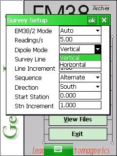
In Manual Mode, select either Horizontal, Vertical, or Both. In the Auto Mode, select either Horizontal or Vertical
4. The Survey Line is the name given to each survey line.
Generally, these are coordinates of the your survey. If the user names the Survey Line by a number, the EM38-MK2 program will automatically name each subsequent line a new number based on the Line Increment. The Line Increment is the distance in which Survey Lines will be from one another. For example, if the first Survey Line is named 2.50 (Y=2.5) and the Line Increment is 2.50, your proceeding lines will be named 5.00, 7.50, 10.00, and so on. In this example, the Start Station and station positions shown during data acquisition would represent a X coordinate along the survey line.
5. The Sequence Field determines whether the user begins each line at the same side or not.
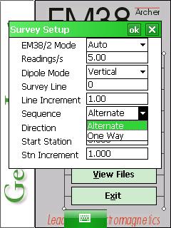
Select determines whether the user is going to conduct each survey line in the same direction (One Way) or alternate the direction of each line (Alternate). Data acquired on a grid is often acquired using the Alternate setting. If using GPS, this may be a moot point as each reading possesses a GPS coordinate attached to it.
6.Select the Line Direction.
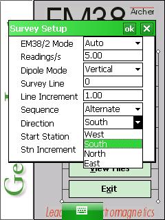
Select a direction (North, West, South, East) from which the first line will be surveyed. If the Sequence is One Way, this setting will stay the same for each data line. If the Sequence is Alternate, the EM38-MK2 will automatically switch the directions for each line with approval. If in doubt and the survey is conducted using a grid, it often works out well for North to represent the direction towards greater positive Y values and East to represent the direction of increasing X values.
7. The Start Station Field is the starting station number for each line.
For instance, if the operator is using the imperial measuring system and starting at X=5 feet away Y axis, the operator may want to put in a measurement of 5.00 or take good notes (or both).
If in the Auto Mode or Manual Mode, the user needs to select a Station Increment. In Auto Mode, the Station Increment field is, in essence, the “reading” increment and may be set to 1 to display the number of measurements acquired. In the Manual Mode it represents the distance between stations along a survey line. Once again, if the value is set to 1, the distance along a survey line represents the number of readings recorded. This value is also used with the Start Station Field to display information with graphics.
8. After changing the EM38-MK2 Survey Setup Menu options, it is important to save.
Press the OK Button to save. After pressing the OK Button, it is safe to push the X Button to exit. If the user exits without pushing the OK Button, the changes will not be saved.