Geonics EM61 Operational Procedures and Quality Control Recommendations
Geophysical Investigations with the Geonics EM61-MK2 and EM61 operational procedures and quality control recommendations.
Geonics EM61 operational procedures and quality control recommendations are different than the “Quality Control for OE Digital Geophysical Mapping” that the U.S. Army Engineering and Support Center USAESCH has defined as standard equipment tests and data quality requirements for its Ordnance and Explosives – Digital Geophysical Mapping OE-DGM contractors.
Poorly functioning equipment is a source of frustration and time delays for geophysical investigations. In order to efficiently and successfully perform a survey, complete these EM61 operational proceduress suggested by Geonics (Geonics EM61 operational procedures and Quality Control Recommendations) to check functionality and quality control.
EM61 Operational Procedures for Before Starting a Geophysical Investigation:
1. Inventory and Inspect the EM61 and all of its accessories. (Out of Box)
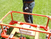
In general, the EM61 will include the electronics assembly, an upper coil assembly, a lower coil assembly, four coil spacers, two cables to connect the upper and lower coil, two cables to connect the lower coil to electronics assembly, two cables to connect the electronics assembly to the data logger, an EM61 handle, a trailer kit (two wheels), EM61 battery packs and battery chargers, a data logger and its charger, a cable to connect the data logger to the PC, a CD with the equipment manual and appropriate computer software, a GPS mount (optional), and the equipment’s shipping cases. Different accessories may be added or subtracted from this list, depending on the rental. Check your Packing List and confirm that everything that you need was sent and is present for geophysical operations.
2. Assemble the Instrument and Power Up. (Out of Box)
Click here to learn how to assemble the EM61. Turn on the EM61 and allow the instrument to warm up by letting it run for 2 to 5 minutes. Batteries should come fully charged. When not in use, it is recommended to charge them.
3. Conduct the Personal Test. (Daily)
After warming up, keep the EM61 in a static position and begin collecting data. The EM61 readings may vary if you are wearing any metal. Remove all sources of interference from your body. Common sources of interference include steel toe boots, keys, coins, cell phones, and ballpoint pens. After removing all obvious sources of interference, the operator should walk close to the EM61 coils while an observer notes any changes in the EM61 readings. Once there is no change, you can perform the next test.
4. Perform the Cable Shake Test. (Daily)
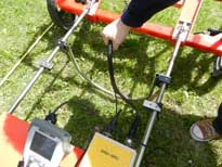
Perform the Shake Test to identify cable shorts and broken pins on the connectors. After concluding the Personal Test, continue to keep the EM61 in a static position while collecting data. Ask an assistant to observe the data, while you shake each EM61 cable. Begin shaking a cable from the one side and continue to shake it until you reach the other end, so that the full length is tested. The assistant should be looking for any spike in the data resulting from the movement. If a spike occurs, that cable needs to be replaced. Make certain to test any replacement cables. Make sure to test all cables.
5. Carry out the Pull Away Test. (Daily if using navigational equipment/towing)
Perform the Pull Away Test to identify the effects of navigational equipment and/or vehicles to tow the EM61. While the equipment is collecting data in a Static Background Test (see below) and navigational and/or vehicles are positioned as they would be during the geophysical investigations, slowly pull away from the EM61 to note any differences in the EM61 readings.
6. Complete the Static Background Test. (Daily)
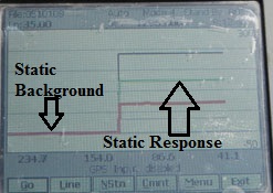
Do a Static Background Test to establish if the EM61 is taking consistent, stable readings. Find an area free of metal and anomalous noise/responses caused by roads, power lines, transmitters, etc that can be used during geophysical investigations for EM61 operational procedures such as nulling. Unstable readings are caused by accompanying noise such as EM transmissions from power lines or an instability in the earth’s magnetic field.
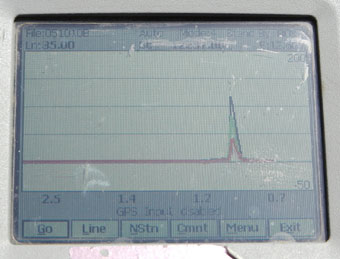
Place the EM61 in the test area at its normal height and orientation, turn it on, and begin recording data. Note the time it takes for the equipment to warm up by watching as the readings begin to stabilize. After the EM61 is warmed up, watch the readings for at least three minutes and make sure there is less than a 20mV deviation. Consistently use this area to null the EM61 during your project unless the geophysical investigation area is very large. In this case, find multiple areas to conduct these tests as the effects of ambient noise may vary across a large project site.
7. Execute the Static Response Test (Daily)
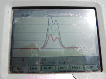
Establish the amplitude of response and instrument drift of a test item such as a standard 2” diameter steel trailer hitch ball by performing the Static Response Test. During the EM61 operational procedures try to keep the EM61 in the same test area as the Static Background Test, position the test item under the EM61 and let it collect data for a minimum of three minutes. Note the amplitude and consistency of the reading, making certain there is less than 5% deviation in response from test to test.
Note, performing the Static Background and Static Response Tests will allow you to properly scale your monitor for the 6 line test, if you use the same test object.
Checklist for Daily Instrument Checks PDF
EM61 Operational Procedures to perform the first day of the Geophysical Investigations:
1. Conduct the 6 Line Test.
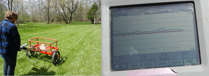
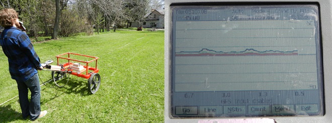
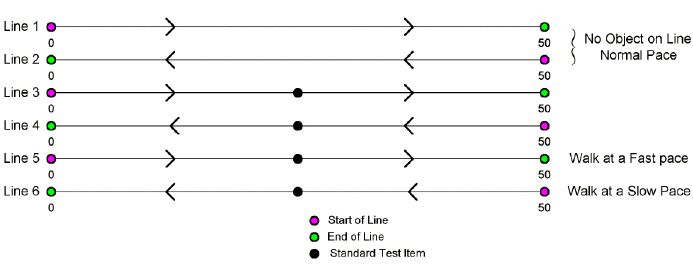
Before any geophysical investigations, perform the 6 Line Test. Power up the EM61 and allow it to warm up for 2 to 5 minutes. Find an area that has little interference and no deviating responses. Identify and clearly mark your test line. Run your wheel along the line for each pass to ensure that the same path is being taken.
Line 1: At a normal pace, begin to collect data along the test line. At the end of the line, pause your recording and turn around.
Line 2: Take a second recording along the test line. These two lines are to establish the background noise over the test area. They should be fairly consistent and mirrored images of each other, if the second line started at the opposite end.
Next, use a standard test item, such as a 2” steel trailer hitch ball, to use for the following four test lines. Stick the steel trailer ball into the ground so that the orientation of the test item is the same at all directions.
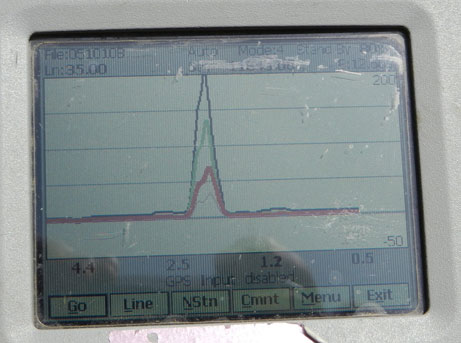
Line 3: Take a third reading along the test line to receive baseline readings of the EM61 test item and the GPS location of the test item (if used). Take note of the EM61 reading and the station location or GPS reading when going over the test item. Note that only corrected GPS locations will be demonstrate repeatability along a short survey line.
Line 4: Take a fourth reading to verify heading effects and the repeatability of the response amplitude. Heading effects are any EM61 reading changes caused by the EM61’s direction and/or orientation. The amplitude of the response to the test item should be similar.
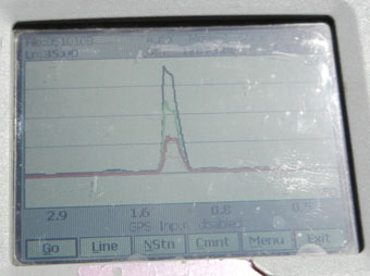
Line 5: Next, take a fifth reading, walking at a slow pace. Observe if there is any latency (time delay) in the reading when passing by the test item. Also, note the GPS location of the test item compared to the reading in Line 3 .Is the positional data accurate?
Line 6: Last, take a sixth reading, walking at a fast pace. Again, observe if there is any latency (time delay) in the reading when passing by the test item. Additionally, note the GPS location of the test item compared to Line 3. Is the positional data accurate?
Checklist for Six Line Test PDF
Six Line Test
Repeat Data:
Examination of Repeat Data
When grid sampling, it is important to have a minimum of 5% repeat data, more if a site has a low density of anomalous responses. When repeat data is compared, you can evaluate the ability of the EM61 to consistently read and evaluate the positional accuracy of the data. Any inaccuracies in repeating the position indicates a problem in the method of navigation.
Other Quality Control Tests:
Wheel Increment Test:
If you are using the Wheel Mode to record data, you must enter a Wheel Increment. Geonics suggests setting the Wheel Increment to 0.66 ft if using the Imperial Measurement System and .2m if using the Standard Measurement Setting. However, entering these numbers assumes the ground traveled is perfectly flat. Often the terrain surveyed is less than ideal and the best value for the wheel increment is slightly different than 0.66 ft. In this case, perform the Wheel Increment Test.
Measure and mark a fixed distance using a tape measure (the longer the better.) Set your Wheel Increment to 1. Record data from the start to the end of the line. Divide the distance of the line by the number of stations recorded.
For instance, if your measured line is 50 feet and you record 81 station intervals then divide 50 by 81.
50/81=.617
Set your Wheel Increment to .617. Now, collect data along your fixed line with the Wheel Increment. Your distance with the new Wheel Increment should match the distance of your measured line.
It may be beneficial to perform this test multiple times before ultimately setting your line increment.
This completes the page on EM61 Operational Procedures
