EM34 Assembly and Initial Setup
EM34 Assembly is quick and easy.
1. Begin EM34 assembly by doing inventory. The EM34 and its accessories arrive in one large shipping case. This shipping case contains a transmitter console, a receiver console, two coils, coil cables, a data logger, data logger cables, three reference cables, and a data logger charger. Other accessories and/or spare parts may also be included. Always check the packing list to verify what was received.
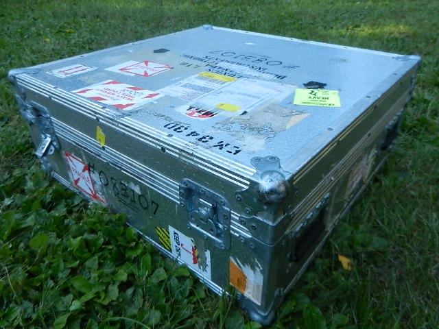
EM34 Shipping Case
When the top of the shipping case is taken off, the user may see this:
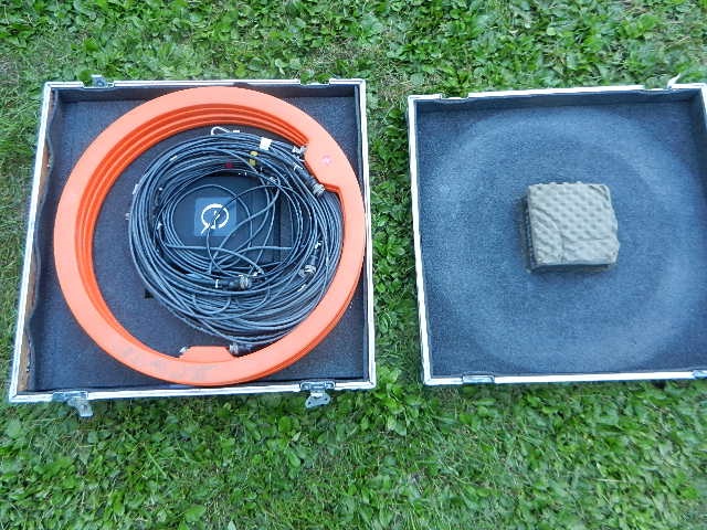
EM34 Coils and Reference Cables
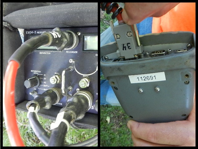
Under the coils and reference cables are more EM34 components, cables, and accessories:
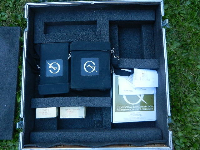
EM34 components, cables, and accessories
2. Before setup, consider choosing an area that will have little noise. Noise can be caused by buried pipes, power lines, nearby buildings, etc. Determine what reference cable will be used for the survey. If multiple reference cables are going to be used, it may be wise to start with the longest reference cable as this is the best length to initially null the instrument. Reference cables come in 10, 20, and 40 meter lengths.
Lay the transmitter console and coil as well as the receiver console and coil across from each other at approximately the length of the chosen reference cable. Make sure that the coils are orientated in the same way. The easiest method to do this is to ensure both coils are laid flat in the ground with their red label, signifying transmitter or receiver, facing up in the same orientation.
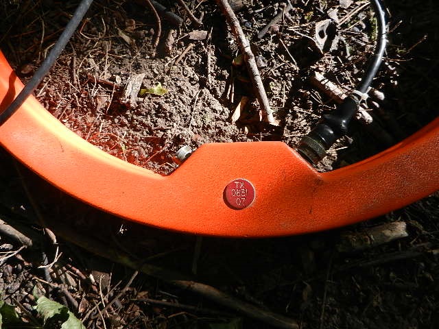
Red Label TX for transmitter
3. Connect the proper cables. Establish which end of the reference cable connects to the transmitter coil and receiver console. Each end of the reference cable contains a metal loop to connect to either the transmitter console or receiver console and a connector to attach to the transmitter coil and receiver console. The distance from the metal loop to the connector is different depending on whether it is attaching to the transmitter or receiver end.
Connect the reference cable end with a longer distance between the metal loop and connector to the transmitter and connect the reference cable end with the shorter distance between the metal loop and the connector to the receiver.
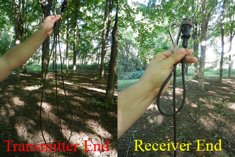
Reference Cable Ends
Connect the reference cable to the transmitter coil and receiver console.
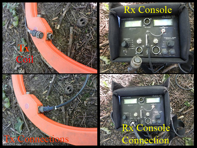
Transmitter Coil and Reciever Console
Note that the transmitter coil has more than one connection port. Make sure to connect the reference cable to the proper 8 pin connection port. Likewise, connect the reference cable to the receiver console port labeled, “Reference.”
Connect the short transmitter cable to the remaining port on the transmitter coil and connect the other end to the transmitter console. Do not connect the receiver console to the receiver coil yet!
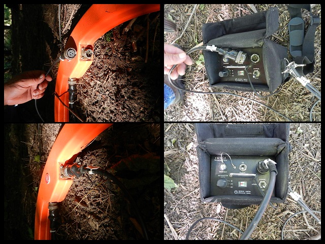
Short Transmitter Cable Connections
Connect the metal loops on each end to the appropriate console.
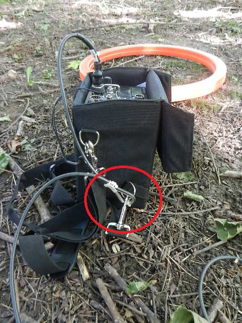
Connect the metal loops of the reference cable
4. Set the coil separation setting. Begin by making certain the power level is set to normal on the transmitter console. Set the coil separation on both the transmitter and receiver coils to the appropriate length. For example, if you are using a 10m reference cable, set both switches to 10m.
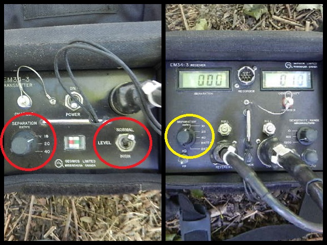
Tx and Rx seperation; Tx level
5. Check the batteries of the transmitter and receiver consoles. For the transmitter batteries, simply turn on the console. A battery monitor meter will display a needle that will be in the green area if the batteries are good or the red area if the batteries are bad. If the batteries seem bad, check the connections before replacing them.
For the receiver batteries, turn the separation value to BATT+/- and push the power button. The batteries need to be replaced if the voltage is lower than +/-4.5. Check the connections before replacing the batteries. New batteries should read about +/-6.0.
Click here to read more about EM34 batteries and how to replace them. LINK HERE
6. Set the coil separation back to the appropriate length. Prepare to null the instrument. As stated earlier, nulling is best done with the largest separation that is going to be used in the field.
Leave the transmitter console ON. With the receiver console ON and the receiver coil disconnected, switch the Sensitivity Range to 1000 m/S. Press the Null button. Both receiver readings should read 0. If either readings do not read zero, release the appropriate locknut by turning it once counter-clockwise and use a flat head screw driver to turn the control potentiometer. Adjust the meters until they read 0. Then retighten the locknuts.
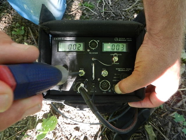
Adjust potentiometers
7. Check the receiver compensation and gain. Finally, connect the receiver console to the receiver coil. Switch the sensitivity to 1000m/S. Assuming the coils are properly orientated, move the receiver coil until the separation meter reads zero (+/-300, In some instances, 0 is impossible). Mark this position.
Now move the coil until the separation value reads 1000. Mark this position. Measure the distance of the spacing. It should be approximately 24.2% of the intercoil spacing.
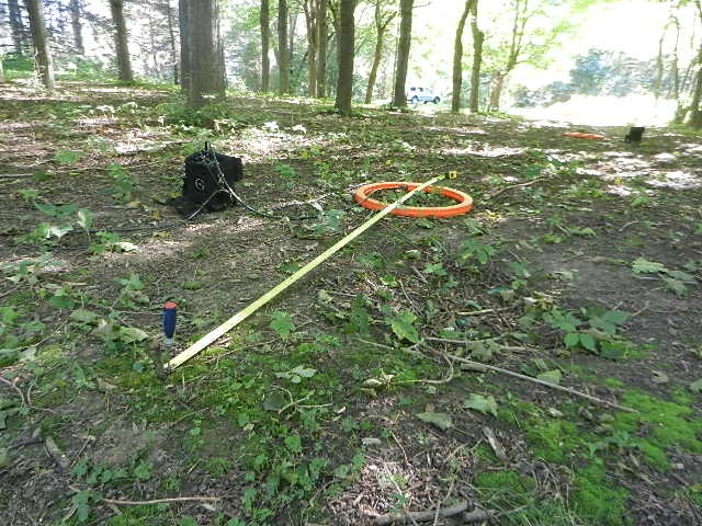
Measuring the spacing between separation values
For instance, in a test at 10m separation, perhaps your spacing measures 95.25 inches:
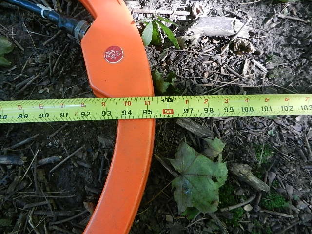
Test Measurement
There is approximately 393.7 inches in 10 meters. 95.25/393.7= 0.2419 or about 24.2%.
8. Move the receiver coil back until it reads 0 separation value. The instrument is now ready to take readings in the vertical or horizontal dipole mode. The sensitivity range should be set as such that the conductivity reading are in the upper 70% of the full scale. To reduce any reading errors, make certain the consoles are approximately a meter away from the coils. If using a data logger, connect the data logger cable to the data logger and the proper port on the receiver. Often this is port 1.
Connecting the EM34 Data Logger